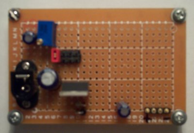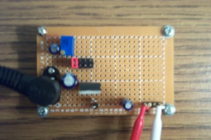
This is a variable voltage 1.5A supply I threw together for bench
experimenting for under $10. With a 24VDC wall wart, this board can produce
anywhere from 23V to 1.2V

 Click on schematic for a PDF version.
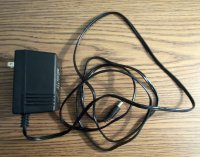
This circuit is based on an Adjustable Regulator design from National Semiconductor's LM317 datasheet. Everything from the wall plug to the diode bridge can be had inside a typical wall wart (I found a wide assortment of these at a second hand store for $1.29 each.) Most wall warts have a capacitor inside too, although it doesn't hurt to add an extra one (C1) on the circuit board.
The jumper block selectable resistors are an improvement I made to allow me to easily select between several fixed voltages. First I built the circuit with only R2, adjusting it for each desired voltage (i.e. 12V, 9V, 5V) at the output, each time powering off the circuit, disconnnecting the jumper and measuring R2's resistance with an ohmmeter. When you build your supply, you could just as easily skip the jumper block and only install R2 if you just want an adjustable supply. If you decide to add the "quick selection resistors" as I did you will need to determine your values experimentally unless you use exactly the same wall wart and choose exactly the same voltages I did (it's unlikely you will.)
Note: R3-R5 are not installed on the board in the photos

I built this circuit in an evening using an experimenter's board from Radio Shack. I also found a mating power connector at "The Shack" for the specific wall wart I used, but if you can't find one it's probably just as easy to cut the power connector off the wall wart and solder the wires directly to the board.
The screws at the board's corners are 1/2" #6 machine screws with nuts holding them to the board. I like to use these for legs (you could also use standoffs) to keep the wiring on the underside of the board off the table.
The blue pot is a 20 turn 5K part I used this because I wanted to adjust the output voltage with extreme accuracy: a cheaper substitute may be sufficient for your needs.
Q: Shouldn't that LM317 be heat sinked?
A: Probably - I like to live dangerously. I did make sure that it doesn't
contact any other circuit components and will probably not pull more than
500mA from it, at the most. It certainly wouldn't hurt to heat sink it
and it will most certainly last longer if you do.
Q: Where can I get more information on the LM317?
A: National Semiconductor has a datasheet
for it on their website which shows many additional applications.
Q: Where did you get the parts?
A: The protoboard and power connector came from Radio Shack. The wall
wart was from the "Salvation Army Thrift Store." I mail ordered the rest
of the parts from Digikey.